What is the CAM normalization process?
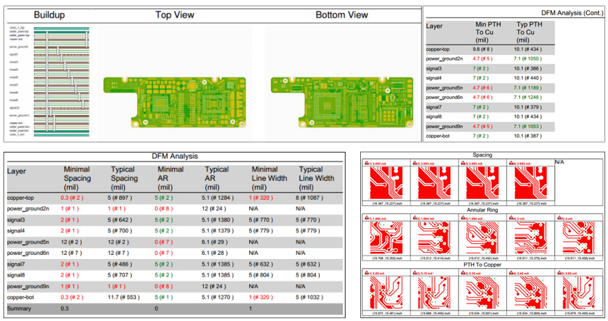
The Basic Steps of the normalization process are:
- Rename the files to our standard naming convention
- Check to ensure that all necessary files are present
- Import Gerber and NC drill files into our CAD system
- Review that the boards’ specifications in the order match the data supplied (based on information in Gerber files, non-Gerber prints and other document files)
- Preparation of files for Custom Spec orders, there are basic modifications that are made to most every set of files received by AdvancedPCB. These modifications are required for our custom spec process and are not intended to alter the functionality of your design in any way.
What is the CAM panelization process?
Can I send the Gerber file directly from my design software?
We strongly recommend the use of a standalone Gerber viewer. What you see is not always what you get. Don't assume that what you see in your design software is what the manufacturer will see. Sometimes, there are wide variations between what the design software shows and the output in the Gerber files. It's wise to use a third-party review to check your design. You will find that files output in a 274-x format will import into most of these packages with no additional configuration needed.
What types of vias do you offer?
We offer exposed, tented, plugged, and filled vias.
How do you process exposed vias?
How do you process tented vias?
How do you process plugged vias?
How do you process filled vias?
How do you process a silkscreen?
How do you process additional markings on the PCB?
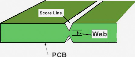
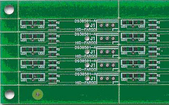
Scoring is a "v" groove cut into the top and bottom surfaces of an array configuration of multiple PCB's or a PCB with removable rails or frame. The cut depth is set such that the material left is the lesser of .018" or 1/3 of the finished thickness. When this process is used the printed circuit boards are typically set up side by side and end to end with no gap between the edges. This results in the v-grove cutting into the area of the boards, so a .015" clearance between the edge of the boards and any conductors is required.
How do I indicate score lines?
When placing an order that requires scoring please indicate this requirement by checking the score option on the order form. If the CAD files supplied with the order already have the boards step and repeated, indicate the locations of the score line in the fabrication or panel print. If you are supplying the CAD data as a 1-up image please supply a drawing with the array configuration that you would like including tooling holes, fiducials and step and repeat requirements. Our standard score angle is 30 degree (blade angle total), but we can also do a 60 degree angle at a premium price.
What do you need from me to set up a scored array?
We can set up your scored array for you (Standard and Advanced PCB orders), If we have:
- Your single board files (1-up files)
- The total number of boards in the array and if the number of boards in the X direction and the Y direction. (boards will be placed edge to edge (0 mils between)
- The width of the Top, bottom, left, and right rails (standard is 0.5"), if required.
- Select “scored array” on your order.
A tab route is used to create arrays, often called "route and retain". The customer can place more than one board (same or different design) up in a given area in an array or panelized configuration. This is typically for the convenience of the customer or for assembly requirements that utilize pick and place machines to load components. The PCB's are then separated by breaking or cutting the tabs. Tabs are usually 0.100" in width and are placed with at least 1 on each side of the boards. The tabs are usually .050" is width.
How do I tab route my board?
How much space should I leave out for tab routing?
What are your PCB manufacturing tolerances?
See tolerance information
here.


